
- Pot CoresOpen or Close
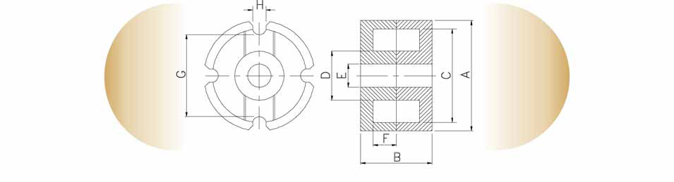
As pot cores are one of the oldest core designs. They are available in a wide range of worldwide standardized sizes - according to IEC 62317-2. Originally produced for filter inductors. pot cores are becoming increasingly popular in power applications. With the introduction of EMC legislation, electromagnetic screening has become a prime concern in core selection. The pot core's shape almost completely encloses the windings and whilst this can be a hindrance for access purpose, it provides excellent screening.Dimensional Details
Part No. Core A
mmB
mmC
mmD
mmE
mmF
mmEffective Parameters ∑l/A
mm-1le
mmAe
mm2Ve
mm3Approx
Weight/
Set
gms/
Set29-290- PC 7×4 7.35-0.25 5.8+0.20 3-0.1 1.4+0.05 2.8+0.2 4.2-0.1 1.43 10 7 70 0.5 29-350- PC 9×5 9.30.3 7.5+0.25 3.9-0.2 2+0.1 3.6+0.3 5.4-0.2 1.25 12.2 9.8 120 0.8 29-400- PC 11×7 11.3-0.4 9+0.4 4.7 -0.2 2+0.1 4.4+0.3 6.6-0.2 1 15.9 15.9 252 1.7 29-450- PC 14×8 14.3-0.5 11.6+0.4 6-0.2 3+0.1 5.6+0.4 8.5-0.3 0.8 20 25 500 3.2 29-500- PC 18×11 18.4-0.8 14.9+0.5 7.6-0.3 3+0.1 7.2+0.4 10.7-0.3 0.6 25.9 43 1120 6 29-550- PC 22×13 22-0.8 17.9+0.6 9.4-0.3 4.4+0.2 9.2+0.4 13.6-0.4 0.5 31.5 63 2000 13 29-600- PC 26×16 26-1 21.2+0.8 11.5-0.4 5.4+0.2 11+0.4 16.3-0.4 0.4 37.5 94 3520 21 29-620- PC 30×19 30.5-1 25+0.8 13.5-0.4 5.4+0.2 13+0.4 19-0.4 0.33 45 136 6120 36 29-6500- PC 36×22 36-1 29.9+0.8 16.2-0.4 5.4+0.2 14.6+0.4 22-0.6 0.26 52 202 10600 57 29-674- PC 42×29 42.4-0.7 36.6+0.6-0.1 17.7-0.6 5.4+0.2 20.3+0.6 29.4+0.2-0.2 0.259 68.6 265 18200 104 29-675- PC 47×28 47-1.3 39+1.1 20-0.6 5.5+0.2 19+0.6 28-0.6 0.232 72.5 312 22600 120 29-680- PC 59×36 59.3-1.8 49+1.3 25.5-0.8 5.5+0.2 23.6+0.8 35.6-0.7 0.181 88 485 42600 229 29-690- PC 80×60 78+2.0 69 33.5-1 9+0.5 43.8+1 60-1 0.164 154.6 945 145700 783 29-200- PM 50×39 50-1.7 39+1.3 20-0.6 54+0.2 26.4+0.8 39-0.4 0.227 84 370 31000 - 29-2010- PM 62×4962-2 65-2 48.8+1.5 25.5-0.8 5.4+0.2 33.4+0.8 49-0.4 0.191 109 570 62000 280 29-2020- PM 74×59 74-2.5 57.5+1.8 29.5-1 54+0.3 40.7+0.8 59-0.6 0.162 128 790 101000 460

Part No. Core F58 P11 F5 F5A F44 F47 F48 F9 F9C F10 F39 F16 F44A 29-290- PC 7×4 - - - - 900/R - - - - - - - - 29-350 PC 9×5 560/R 1300/R - - 1160/R - 1400/R 2500/R 2700/R 4000/R 5000Y - - 29-400- PC 11×7 780/R 1600/R - 1880/R 1580/R 1455/R 1600/R 3500/R 3800/R - - - - 29-450- PC 14×8 970/R 2300/R - 2500/R 2090/R 1875/R 2100/R 4600/R - - 9800/Y 130±25% 2800/R 29-500- PC 18×11 1300/R 2900/R 2800/R 3075/R 2600/R 2500/R - 5600/R 6000/R 6450/R 12600Y - 3600/R 29-550- PC 22×13 1710/R 3800/R - 4650/R 3500/R - - 6860/R - 8600/R 16000Y - 4400/R 29-600- PC 26×16 - 5200/R - 6000/R 4650/R - - 9000/R - 12000/R 20000Y - 5500/R 29-620- PC 30×19 - 6300/R 6412/R 7500/R 6000/R - - 10500/R - 14500/R - - 6400/R 29-6500- PC 36×22 - 8400/R - - 7600/R - - 15200/R - - 21000Y - - 29-674- PC 42×29 - 9500/R - 10500/R - - - 16600±25% - - - - - 29-675- PC 47×28 - - 10460/R - - - - 17500/R - - - - - 29-680- PC 59×36 - 12500/R - 13850/R - - - - - - - 6500/R - 29-690- PC 80×60 - - - - - - - - - - - - - 29-200- PM 50×39 - - 7400/R - - - - - - - - - - 29-2010- PM 62×49 - - 9200/R - - - 9200/R - - - - - - 29-2020- PM 74×59 - - 10000/R - - - 10000/R - - - - - - R-+30%, -20%
Y-+40%, -30% All Values mentioned above are for an ungapped pair of cores
Gapped values can be provided on request
Adjusters to suit all the above cores are available on request
All above cores are also available with Solid Center Spigot.
All above cores are available in other materials on request. - 4 Slot Pot CoresOpen or Close
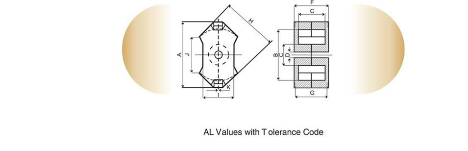
 MMG India offer a wide range of 4 Slot Pot cores based on the old 'VlNKOR' series. The cores are supplied gapped to an effective permeability range and are adjustable for tuned filters up to 5MHz. The larger cross-sectional area offered by the 4 Slot range allows for a higher power setting than the conventional 2 Slot version. Also with the advantage of 2 more slots they can be used in applications where 1/2 and 1/4 turns are required. A full range of bobbins and mounting assemblies are also available.Dimensional Details
Part No. Core A
mmB
mmC
mmD
mmE
mmF
mmEffective Parameters le
mmAe
mm2Ve
mm3P11 29-1040- 14×9 14±0.3 4.50±0.5 11.66±0.25 6.05±0.15 3.63+0.02-0.03 2.90±0.10 18.70 25.90 484 - 29-1080 18×11 18±0.38 11.20±0.10 15.17±0.33 7.94±0.20 4.56±0.09 3.70±0.10 24.70 44.30 1090 3280R 29-1120- 21×14 21±0.05 13.60±0.10 18.08±0.39 9.64±0.23 4.63±0.02 4.40±0.10 30.70 73.20 2220 4290R 29-1160- 25×16 25.4±0.53 21.5±0.44 16±0.10 11.32±0.27 5.33±0.13 5.20±0.10 36.40 99.90 3630 5210R 29-1200- 30×19 39.49±0.61 18.80±0.10 24.4±0.52 13.72±0.33 5.20±Min 6.10±0.10 43.20 153 6590 7270R 29-1240- 35×23 35.5±0.75 22.8±0.12 29.31±0.6 16.2±0.4 5.2Min 7.39±0.1 52.50 223 11700 8690R 29-1280- 45×29 45±0.92 29.20±0.10 37.34±0.79 20.19±0.49 5.225±0.10 9.50±.10 67.00 362 24300 11040R R+30%, -20% Gapped values can be provided on request
All above cores are also available with Solid Center Spigot.
All above cores are available in other materials on request. - Wide Slot CoresOpen or Close
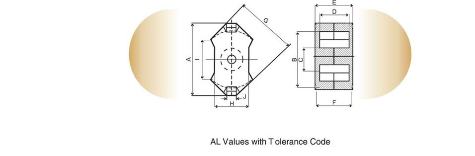
 These cores are used extensively in telecommunications and converter power supply circuits. The wide slot in the lower half of the assembly enables a large number of connections to be brought out. These cores are also referred to as Touch Tone (TT) pot cores as were originally designed for push-button telephone sets.(CC Cores / Touch tone Cores) Dimensional details & AL Values with tolerance code
R +30%, -20%Part No. Core A
mmB
mmC
mmD
mmE
mmF
mmG
mmH
mmEffective Parameters le
mmAe
mm2Ve
mm3P11 F5 F44A F9 F10 F39 29-652- 14×8 13.8+0.5 11.6+0.4 5.8+0.2 3+0.2 5.6+0.4 8.5+0.5 9.4±0.15 8.65±0.3 25.3 25.3 539 2000R 1800R 1700R 3800R 5000R 7000R 29-632 23×11 22.4+0.9 18+0.6 9.5+0.4 5+0.2 7.4+0.4 11+0.2 15.25+0.25-0.25 13.2-0 31.2 68.8 2144 4375R 4000R 3850R 7200R 10000R 16000R 29-635 23×18 22.4+0.9 18+0.6 9.5+0.4 5+0.2 14.0+0.6 18.2+0.2 15.25+0.25 13.2-0 45.1 73.1 3293 2720R 2500R 2400R 5300R 7000R 12000R 29-637 30×19 29.5+1.0 25+0.8 13.1+0.4 5.4+0.4 13.0+0.4 19+0.4 20.2+0.3-0.3 18+0.5-0.5 46.4 119 5534 5400R 4700R 4500R 8000R 11100R 18500R - RM Cores - RegularOpen or Close
RM cores arose due the demand for the coil formers with integrated pins that allows for efficient winding and high PCB packing densities. Clamps engaging in recesses in the core base hold the cores place, meaning glue is not normally required in this process All the cores adhere to specifications laid down in IEC 62317-4 and in DIN 41980.
RM cores are designated for two main applications:
- Highly stable, extremely low loss filters inductors and other resonance determining inductors (F58,P11)
- Low distortion broadband transmission at low signal modulation (F39,F10,F9)
RM cores also be supplied without the centre hole. These have a higher AL value and cross sectional area and are used for power applications (F47,F44,F5A)
Dimensional DetailsPart No. Core A
mmB
mmC
mmD
mmE
mmF
mmG
mmH
mmEffective Parameters ∑l/A
mm-1le
mmAe
mm2Ve
mm3Approx
Weight/Set
gms/Set29-900- RM4 11-0.4 8+0.3 3.9-0.2 2+0.1 7+0.4 10.5-0.2 9+0.25-0.25 9.8-0.4 1.9 21 11 232 1.45 29-700- RM5 14.6-0.6 10.2+0.4 4.9-0.2 2+0.1 6.3+0.4 10.5-0.2 9+0.25-0.25 12.3-0.5 1 20.8 20.8 430 2.9 29-730- RM6 17.9-0.6 12.4+0.5 6.4-0.2 3+0.1 8+0.4 12.5-0.2 10.34+0.25-0.25 14.7-0.6 0.86 26.9 31.3 840 4.9 29-7600- RM7 20.3-0.8 14.75+0.65 7.25-0.3 3+0.1 8.5+0.4 13.5-0.2 11.3+0.25-0.25 17.2-0.7 0.74 29.8 40 1200 6.5 29-790- RM8 23.2-0.9 17+0.6 8.55-0.3 4.4+0.2 10.8+0.4 16.5-0.2 14.3+0.25-0.25 19.7-0.8 0.67 35.50 52 1850 10.3 29-830- RM10 28.5-1.3 21.2+0.9 10.9-0.4 5.4+0.2 12.4+0.6 18.7-0.2 16.2+0.25-0.25 24.7-1.1 0.5 42 83 3470 20 29-9xx- RM12 37.6-1.5 24.9+1.1 12.8-0.4 5.4+0.2 16.8+0.6 24.6-0.2 21.6+0.25-0.25 29.8-1.2 0.39 56.6 146 8340 44 29-880- RM14 42.2-1.2 29+1 15-0.5 5.4+0.2 20.8+0.6 30.2-0.2 27+0.25-0.25 34.8-1.3 0.35 70 200 14000 72 29-950- R6 17.6-0.6 12.4+0.4 6.4-0.2 3+0.1 8+0.4 12.5-0.2 10.34+0.25-0.25 14.7-0.5 0.8 25.6 32 820 5.1
Part No. Core F58 P11 F5 F5A F5C F44 F47 F9 F9C F10 F39 F44A 29-900- RM4 - 900R - - - 800R - 1700R - 2800R 3700Y 1100R 29-700- RM5 - 1800R - - 2600R 1570R - 3170R 6000Y 5200R 6700Y 1800R 29-730- RM6 890R 2000R 2250R - 3100R 2200R - 4625R 4270R 6200R 8600Y 2200R 29-7600- RM7 - 2800R - 2850R 3400R 2370R - 4690R 5040R 7000R 10000Y 2700R 29-790- RM8 1170R 2500R 3000R 4000R 4300R 2906R - 5700R 5670R 8375R 12500Y 3300R 29-830- RM10 1600R 3960R 4000R 4490R 3300+60% 3800R 3650R 7600R 8060R 11000R 16000Y 4200R 29-9xx- RM12 - - 4400R 8500R 6000R 5000R 4750R 8400R - 12800R - 5300R 29-880- RM14 - - - 6600R 6800R 6000R 5400R 9500R - - - 6000R 29-950- R6 732R 2300R - - - - - 4300R 4900R 6000R 8600Y - R- +30%, -20%
Y- +40%, -30% All Values mentioned above are for an ungapped pair of cores
Gapped values can be provided on request
Adjusters to suit all the above cores are available on request
All above cores are also available with Solid Center Spigot.
All above cores are available in other materials on request. - RM Cores - Low profileOpen or Close
The increasing miniaturization of electronic circuits and Switched Mode power supplies being integrated into PCB philosophy, low profile components are necessary to overcome height restrictions. In some cases the conventional Windings can be replaced by printed circuit tracks directly onto the PCB.
The RM core's low profile shape and ease of construction give significant advantages including, fast error free winding and efficient repeatable performance.Dimensional DetailsPart No. Core A
mmB
mmC
mmD
mmE
mmF
mmG
mmEffective Parameters ∑l/A
mm-1le
mmAe
mm2Ve
mm3Approx
Weight/Set
gms/Set29-210- RM4 LP 11-0.4 8+0.3 3.9-0.2 4.3+0.4 7.8-0.2 6.3+0.2-0.2 9.8-0.4 1.2 17.3 14.5 251 1.2 29-2100- RM5 LP 14.6-0.6 10.2+0.4 4.9-0.2 3.6+0.4 7.8-0.2 6.3+0.2-0.2 12.3-0.5 0.17 17.5 24.5 430 2.6 29-220- RM6 LP 17.9-0.6 12.4+0.5 6.4-0.2 4.5+0.4 9-0.2 6.84+0.2-0.2 14.7-0.6 0.58 21.8 37.5 820 4 29-230- RM7 LP 20.3-0.8 14.75+0.65 7.25-0.3 4.7+0.5 9.8-0.2 7.8+0.25-0.25 17.2-0.7 0.52 23.5 45.3 1060 5.7 29-240- RM8 LP 23.2-0.9 17+0.6 8.55-0.3 5.9+0.4 11.6-0.2 9.4+0.25-0.25 19.7-0.8 0.44 28.7 64.9 1860 9.2 29-250- RM10 LP 28.5-1.3 21.2+0.9 10.9-0.4 6.7+0.4 13.2-0.2 10.5+0.25-0.25 24.7-1.1 0.34 33.9 99.1 3360 17.2 29-260- RM12 LP 37.6-1.5 24.9+1.1 12.8-0.4 9+0.5 16.8-0.2 13.8+0.25-0.25 29.5-1.2 0.28 42 147.5 6195 33.6 29-270- RM14 LP 42.2-1.2 29+1 15-0.5 11.1+0.6 20.5-0.2 17.3+0.25-0.25 34.8-1.3 0.25 50.9 201 10230 55
Part No. Core F44 F47 F48 F9C F10 F39 F44A F45 29-210- RM4 LP - - - - - 5000Y 1200R - 29-2100- RM5 LP - - - - - 7700Y 2400R - 29-220- RM6 LP 2500R 2400R - 5500R 6600R 10500Y 3000R 2600R 29-230- RM7 LP - - 3120R - - 11500Y 3300R - 29-240- RM8 LP 3600R - - 7050R - 15000Y 4100R 3750R 29-250- RM10 LP 4700R - - 10500R - 19500Y 5200R 4900R 29-260- RM12 LP 6000R 5600R - 12750R - 23800Y 6300R 6300R 29-270- RM14 LP 6710R 6280R - 16275R - 26640Y 7100R 7040R R- +30%, -20%
Y- +40%, -30% All Values mentioned above are for an ungapped pair of cores
Gapped values can be provided on request
Adjusters to suit all the above cores are available on request
All above cores are also available with Solid Center Spigot.
All above cores are available in other materials on request. - EE CoresOpen or Close
EE Cores were one of the first ferrite cores to be manufactured, being derived from their respective iron lamination size. Having rectangular limbs they are relatively easy to manufacture and as such a vast range exists in the marketplace. MMG-India's range reflects a selection of cores that have become, over many years, worldwide standards through continued use. E cores are particularly suitable for power transformers and filters at low frequencies. They are not suitable in high frequency applications as the rectangular centre limb leads to higher leakage inductance and winding resistance. EE cores are available in a range of sizes and materials as per IEC 62317-8

Dimensional Details & AL values with Tolerance Code
Part No. Core A
mmB
mmC
mmD
mmE
mmF
mmle
mmAe
mm2Ve
mm3F5 F9 F5A F44 F48 F9C F10 32-200- EF12.6 12.6+0.5-0.4 6.5-0.2 3.7-0.3 4.5+0.3 8.9+0.6 3.7-0.3 29.6 13.0 384 - - - 760/R - - - 32-040- E13/6.6/3 12.7±0.25 6.6±0.05 3.18±0.2 5.105±0.155 9.725±0.725 3.18±0.2 31.70 9.68 307 550/R - - - 600/R - - 32-370- E16/8/5 16+0.7-0.5 8.2-0.3 4.7-0.4 5.7+0.4 11.3+0.6 4.7-0.3 37.6 20.1 754 1000/R 1400/R - 960R 1100/R - - 32-140- E20/10/5 20+0.7-0.4 10.1+0.1-0.3 5.3-0.4 6.5±0.2 13.1±0.3 5.00±0.2 43 31 1330 1500/R 2500/R - 1390/R 1550/R - - 32-180- EF20/10/6 20.4-0.8 9.95±0.15 5.9-0.4 7+0.3 14.1+0.6 5.9-0.3 44.9 33.5 1500 1300/R 2500/R - 1300/R 1450/R - - 32-160- E19/8/5 19.3±0.5 8.085±0.115 4.75±0.18 5.75±0.125 14.5±0.53 4.75±0.18 40 22.5 900 - 2160/R 1190/R 970/R - 2350/R 2650/R 32-190- E25/13/7 25+0.8-0.7 12.8-0.5 7.5-0.6 8.7+0.5 17.5+0.8 7.5-0.5 57.5 52.5 3020 1750/R 3100/R - 1712/R 1900/R - - 32-030- E25/9.5/6 25.4±0.63 9.53±0.13 6.27±0.2 6.49±0.19 19.56±0.51 6.27±0.2 48.70 38.10 1860 2000/R - 1830/R 1480/R - - 4000/R 32-130- E30/15/7 30+0.8-0.6 15.2-0.4 7.3-0.5 9.7+0.5 19.5+0.8 7.2-0.5 67 60 4000 1800/R 3300/R - 1800/R - - - 32-010- E34/13/8 34.14±0.86 13.11±0.1 7.87±0.18 8.485±0.205 24.59±0.63 11.12±0.25 62.50 77.4 4840 2240/R 4100/R - 2360/R - - - 32-020- E41/22/9 41±1.27 22.28±0.1 8.78±0.19 16.715±0.455 28.58±0.53 11.76±0.20 102 105 10600 - - - 2000/R - - - 32-110- E42/21/15 42+1-0.7 21.2-0.4 15.2-0.5 14.8+0.6 29.5+1.2 12.2-0.5 97 181 17600 3500/R - - 3500/R 4200/R - - 32-120- E42/21/20 42+1-0.7 21.2-0.4 20-0.6 14.8+0.6 29.5+1.2 12.2-0.5 98 240 23300 4750/R - - 4560/R - - - 32-150- E55/27/21 55+1.2-0.9 27.8-0.6 21-0.6 18.5+0.8 37.5+1.2 17.2-0.5 120 354 42500 5800/R 10000/R - - 6050/R - - 32-240- E65/32/27 65+1.5-1.2 32.8-0.6 26.8+0.6 22.2+0.7 44.2+1.5 20-0.7 147-0.0 532 78200 - - 10250/R 7430/R 7840/R - - 32-250- E70/32/32 70±1.35 32+0.5 31.75±0.33 21.57±0.17 48.38±0.75 22.13±0.35 146.27 691.03 101076 - - 11125/R 9060/R 11100 - - R- +30%, -20%
Y- +40%, -30% All Values mentioned above are for an ungapped pair of cores
Gapped values can be provided on request
All above cores are available in other materials on request. - Planar E CoresOpen or Close
Many new electronics equipment will use switched mode power supplies where the voltage transformation unit is integrated on a circuit card. As cards may be racked with minimal clearances. low profile components are necessary. Planar assemblies differ radically from conventional transformers as wire windings are replaced by stacks or flat spiral laminations. In some cases the winding can be replaced by printing circuit tracks, with the E core inserted through the board. The planar E core's low profile shape and ease of construction offers significant advantages including: Fast error-free winding; excellent heat sinking properties and efficient repeatable performance at low cost. All the cores adhere to specifications laid down in IEC 62317-9

Part No. Core A
mmB
mmC
mmD
mmE
mmF
mmG
mmEffective Parameters le
mmAe
mm2Ve
mm3F44 F48 F47 32-9140- EE14×3.5×5 14±0.3 3.5±0.1 4.9±0.2 11±0.25 2.9±0.15 2.05±0.15 - 20.70 14.50 300 - - 1100±25% 32/33-9140- E+l 14 14±0.3 - 4.9±0.2 - - - 1.50±0.05 16.70 14.50 240 - - 1300±25% 32-9180- EE18×4×10 18±0.35 4±0.10 10±0.2 14±0.3 3.95±0.15 2.05±0.15 - 24.30 39.50 960 - - 2700±25% 32/33-9140- E+l 18 18±0.35 - 10±0.2 - - - 2.0±0.1 20.30 39.50 800 - 2900/R 3100±25% 32-9210- EE22×5.7×15.8 21.8±0.4 5.7±0.1 15.8±0.3 16.8±0.4 4.9±0.2 3.20±0.1 - 32.50 78.50 2550 - - 4300±25% 32/33-9210- E+l 22 21.8±0.4 - 15.8±0.3 - - - 2.5±0.05 26.1 78.50 2040 - - 5000±25% 32-9320- EE31.8×6.3×20.3 31.75±0.64 6.35±0.13 20.32±0.41 25.4±0.5 6.28±0.2 3.23±0.15 - 41.70 129 5380 6425±25% - 5900±25% 32/33-9320- E+l 31.8 31.75±0.64 - 20.32±0.41 - - - 3.18±0.13 35.90 129 4560 7350±25% - 6780±25% 32-9380- EE38.1×8.26×25.4 38.1±0.76 8.26±0.13 25.4±0.51 30.85±0.6 7.6±0.2 4.52±0.2 - 52.60 194 10200 7940±25% - 7250±25% 32/33-9380- E+l 38.1 38.1±0.76 - 25.4±0.51 - - - 3.18±0.13 43.70 194 8460 9290±25% - 8500±25% 32-9640- EE63.8×10.2×50.3 63.8±1.3 10.2±0.13 50.3±1 53.6±1.1 10.2±0.2 5.17±0.2 - 79.70 511 40700 13300±25% - 12720±25% 32/33-9640- E+l 63.8 63.8±1.3 - 50.3±1 - - - 5.08±0.13 69.60 511 35500 15050±25% - 14360±25% All Above Cores are available in clipped version for clamping purpose.
- Planar ER CoresOpen or Close
MMG India offers low profile ER cores for SMD transformer application in power, signal and high permeability grades and these cores can also be gapped to suit customer requirements. Key features are; Very low total height, Low stray inductance, and High DC magnetic bias. Suitable applications are; Low power DC-DC converters, Pulse transformers, Broadband transformers, and Driver transformers. Planar ER cores are available in a range of sizes and materials as per IEC62317-9

Part No. Core A
mmB
mmC
mmD
mmE
mmF
mmG
mmle
mmAe
mm2Ve
mm3F44 F47 F48 F49 32-869- ER 9.5×5 9.5-0.3 7.5+0.25 3.5-0.2 7.00Mini. 5-0.2 1.6+0.15 5-0.2 13.6 8.81 120 740R 720/R 800R 4500Y 32-870- ER 11×5 11.00-0.35 8.7+0.3 4.25-0.2 7.90Mini. 6-0.2 1.5+0.15 5-0.2 14.1 12.4 174 1100R - 1200R 6400Y 32-880- ER 14.5×6 14.5±0.2 11.8±0.2 4.7±0.1 - 6.7±0.1 1.65±0.1 5.9±0.2 19 17.6 333 1500R - 1500R - R- +30%, -20%
Y- +40%, -30% All Values mentioned above are for an ungapped pair of cores
Gapped values can be provided on request
All above cores are available in other materials on request. - ETD CoresOpen or Close
ETD (Economical Transformer Design) cores were developed specifically for Power Transformer cores used in Switched Mode power supplies. The combined cross-sectional area of the two outer limbs equals the cross-sectional area of the centre limb allowing an even flux distribution throughout the core. This ensures the absence of localised 'hot spots' that can reduce performance at high frequencies or high flux levels. Their round centre limb provides for minimal winding resistance, leakage inductance and copper eddy current losses. ETD Cores are available in a range of sizes and materials as per IEC 62317-6 together with their associated coil formers (both Horizontal and Vertical mounting) and clips.
 Dimensional details & AL Values with Tolerance Code
Part No. Core A
mmB
mmC
mmD
mmE
mmF
mmEffective Parameters le
mmAe
mm2Ve
mm3F5 F9 F5A F44 F48 F9C F10 32-580- ETD29/16/10 30.6-1.6 16+0.4 9.8-0.6 22+1.4 9.8-0.6 10.7+0.6 70.4 76 5376 - - 2350/R 1950/R 2250/R - - 32-500- ETD34/17/11 34+1-0.6 17.5-0.4 11.1-0.6 25.6+1.4 11.1-0.6 11.8+0.6 78.6 97.10 7640 2400/R - 2840/R 2250/R 2711/R - - 32-520- ETD39/20/13 38.9+1.1-0.7 20-0.4 12.8-0.6 29.3+1.6 12.8-0.6 14.2+0.8 92.20 125 11500 2700/R - 3210/R 2470/R 2800/R - - 32-540- ETD44/25/15 43.8+1.2-0.8 22.5-0.4 15.2-0.8 32.5+1.6 15.2-0.8 16.1+0.8 103 173 17800 3300/R - 3920/R 3100/R - - - 32-560- ETD49/25/17 48.5+1.3-0.9 24.9-0.4 16.7-0.8 36.1+1.8 16.7-0.8 17.80Mini 114 211 24000 3700/R - 4400/R 3525/R 4090/R - - 32-490- ETD59/31/22 59.8+1.4 31.2-0.4 22.1-0.9 43.6+2.2 22.1-0.9 22+0.9 139 368 51200 5000/R - - 4900/R 5800/R - - R- +30%, -20%
Y- +40%, -30% All Values mentioned above are for an ungapped pair of cores
Gapped values can be provided on request
All above cores are available in other materials on request. - EFD CoresOpen or Close
EFD (Economical Flat Design) cores were developed to meet the increasing demand for low profile components in power transformer design. A combination of very low height and excellent throughput power, when compared to other cores of a similar height, make these cores ideal where space considerations are a priority. EFD Cores are available in a range of sizes and materials as per IEC 6231 7-14 together with their associated coil formers and clips.

Part No. Core A B C D E F G le
mmAe
mm2Ve
mm3F44 F47 F48 32-720- EFD 15×8×5 15±0.4 7.5+0.15 4.65±0.15 11±0.35 5.55±0.2 2.4±0.1 5.3±0.15 34 15 510 675R 650R 780R 32-740- EFD 20×10×7 20±0.55 10±0.15 6.65±0.15 15.4±0.5 7.75±0.2 3.6±0.15 8.9±0.2 47 31 1460 1120R 1075R 1200/R 32-760- EFD 25×13×9 25±0.65 12.5±0.15 9.1±0.2 18.7±0.6 9.3±0.25 5.2±0.15 11.4±0.2 57 58 3300 1790R 1720R 2200R R- +30%, -20%
Y- +40%, -30% All Values mentioned above are for an ungapped pair of cores
Gapped values can be provided on request
All above cores are available in other materials on request. - EP CoresOpen or Close
EP Cores have a particularly compact, low profile shape and offer excellent shielding from adjacent cores due to the winding being almost completely surrounded by the ferrite core. This allows for high packing densities on printed circuit boards. Originally designed for broadband, small power transformers and signal transmission applications, EP cores are well suited for the demanding properties required from modern electronic components.
EP Cores are available in a range of sizes and materials as per IEC 62317-5.
All Dimensional Details in mm.Part No. Core A B C D E F le
mmAe
mm2Ve
mm332-810- EP7 9.4-0.4 7.2+0.4 3.4-0.2 6.5-0.3 5+0.4 7.5-0.2 15.7 10.3 162 32-820- EP10 11.8-0.6 9.2+0.4 3.45-0.3 7.85-0.4 7.2+0.4 10.4-0.2 19.2 11.3 217 32-800- EP13 12.8-0.6 9.7+0.6 4.5-0.3 9-0.4 9+0.4 13-0.3 24.2 19.5 472 32-830- EP17 18.4-0.8 11.6+0.8 5.85-0.35 11.25-0.5 11+0.6 17-0.6 28.5 33.9 966 32-840- EP20 24.5-1 16.1+0.8 9-0.5 15.3-0.7 14+0.6 21.6-0.4 40 78 3120 32-850- EOP7 9.2±0.2 7.4±0.2 3.3±0.1 8.8±0.2 4.8±0.2 7.4±0.1 15.6 17.7 276 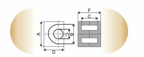
All Values with Tolerance Code.
Part No. Core P11 F5 F5A F44 F44A F47 F48 F9 F10 F39 FTA 32-810- EP7 980/R 1200/R 1200/R 920/R 1100/R 960/R 1100/R 2000/R 3400/R 5200/Y 5200/Y 32-820- EP10 940/R - 1063/R 855/R 1100/R 980/R 980/R 2000/R 3200/R 4800/Y - 32-800- EP13 1500/R 1275/R 1460/R 1235/R 1600/R 1300/R 1400/R 2800/R 4400/R 7000/Y 7000/Y 32-830- EP17 2250/R 2300/R - 2130/R 2400/R - 2400/R 4300/R 6875/R 11400/Y - 32-840- EP20 - - 4100/R 4000/R - - 3900/R 6700/R 11200/R 18700/Y - 32-850- EOP7 - - - - - - - - - - 8780/Y R- +30%, -20%
Y- +40%, -30% All Values mentioned above are for an ungapped pair of cores
Gapped values can be provided on request
All above cores are available in other materials on request. - EQ Cores, PQ CoresOpen or Close
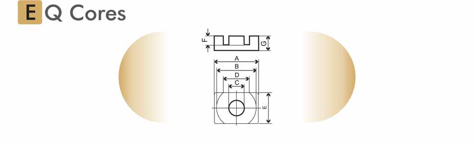
Part No. Core A
mmB
mmC
mmD
mmE
mmF
mmG
mmle
mmAe
mm2Ve
mm3F47 F48 F49 FTA 32-670- EQ 20 20±0.35 18±0.35 8.8±0.15 12.86±0.35 14±0.3 4.1±0.15 6.3±0.1 33.2 59.0 1960 - 3500±25 - 13500+40%-30% 32-640 EQ 25 25±0.4 22±0.4 11±0.2 14.5Min 18±0.3 5.15±0.15 8.0±0.1 41.4 100 4145 4200+30%-20% - 2150+30%-20% 21300+40%-30% 32-650 EQ 25 LP 25±0.4 22±0.4 11±0.2 14.5Min 18±0.3 3.1±0.15 5.3±0.05 - - - 5500+30%-20% - - - 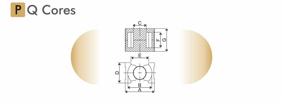
Part No. Core A
mmB
mmC
mmD
mmE
mmF
mmG
mmle
mmAe
mm2Ve
mm3F48 F49 29-060- PQ 26×20 27.3±0.46 22.5±0.46 12±0.2 19±0.45 15.50Min 11.5±0.3 20.2±0.25 45 121 5470 - 3000±25% 29-070- PQ 26×25 27.3±0.46 22.5±0.46 12±0.2 19±0.45 15.50Min 16.1±0.3 24.7±0.25 54.30 120 6530 5250±25% 2500±25% As per IEC 62317-13
All Values mentioned above are for an ungapped pair of cores
Gapped values can be provided on request
All above cores are available in other materials on request. - UU Cores, UR CoresOpen or Close
These cores are used for the construction of transformers in the frequency range from 10 to 500 kHz. The transferable outputs will be determined by core geometry and the upper frequency limits by the material selected. In previous years a major application was for in line transformers producing an electron deflection beam for CRT's. Materials used for these applications are characterized by high flux density, low specific power losses and the decline of losses dependent on temperature in the range from 200 to 1000C.

Dimensional details & AL Values with Tolerance Code
Part No. Core A
mmB
mmC
mmD
mmE
mmF
mmle
mmAe
mm2Ve
mm3F5 F5A F9 F10 F39 F44 F48 F49 34-009- U 10.5 10.5+0.2-0.2 7.9±0.2 5.2+0.3 5.3+0.15-0.15 2.70-0.3 5.5+0.2 40 13 520 800/R - 1000/R 1700/R 2400/Y - - - 34-490- U 12.7 12.7±0.38 6.35±0.05 4.95±0.25 3.81±0.18 2.54±0.13 7.30Mini 33 12.60 416 - - 1000/R - - - - - 34-010- U15/11/6.5 15.5+0.7 11.2+0.5-0.5 6.45±0.25 6±0.25 5.00 5+0.4 48 32 1540 1200/R - 2625/R - 5000/Y - - - 34-015- U25/20/13 24.75±0.75 19.43+0.57-0.58 12.75±0.25 11.33+0.32 8.0Mini 8.25±0.25 86 105 9030 - - 4120/R - - - - - 34-540- U26.5/20.2/9.7 26.54±0.78 20.07±0.13 9.40±0.25 14.60±0.13 - 7.87±0.5 95.40 60.90 5724 - 1790/R - - - - - - 34-025- U31/15.5/16 314±0.6 16.3±0.3 16.3±0.3 8.5±0.5 7±0.5 17.0±0.4 90 112 10079 - - 4500+30%-10% - - - - - 34-521- U37/25/18 36.9±0.8 25.2±0.20 18±0.4 16.30Mini 14.7±0.3 14.9±0.1 125 150 18750 - 3125/R - - - - - - 34-041- U46/20/28 47±0.8 40±0.4 28±0.6 25.8±0.25 - 19±0.85 - - - - 5880/R - - - - - - 34-520- U60/36/23 60.50Nomi 35.8±0.2 23.0±0.4 26.5±0.4 17.0±0.4 26.75±0.75 189 210 39700 2410/R - - - - - - - 34-537- U82/44/60 80.8±1.2 44.53±0.2 - 30.53±0.25 15.0±0.25 50.80Mini 268.6 177.20 47600 - 1810/R - - - - - - 34-544- U91/44.4/15 91±1.36 44.53±0.2 15.0±0.25 30.53±0.25 15.0±0.25 61.0Mini 275.2 177.20 48751.3 - 1810/R - 2410/R - - - - 34-050- U93/76/30 93±1.8 76±0.5 30±0.6 48±0.90 - 36.2±1.2 352.98 847.98 299320 - - - - - 5440/R 6000/R - 34-029- U101.6/57/
25.4104.14Max 57.15±0.38 25.4±0.76 31.75±0.25 - 49.78Mini 308.39 645.16 198965 - - - - - 4500/R 5060/R 6000±25% - Toroid CoresOpen or Close
Ring cores or Toroids manufactured from ferrites offer an efficient shape for variety of wide band, pulse, power transformers and inductors. Toroids Cores are available in a range of sizes and materials as per lEC 62317-12

Dimensional details & AL Values with Tolerance CodePart No. Core A
mmB
mmC
mmle
mmAe
mm2Ve
mm3F5A P12 F8 F9 F9C F14 F19 F5C F10 F39 F47 F48 F44 F16 F57 F5 28-0611- T4.5×2.5×2.0 4.5±1.8 2.495±0.125 2.0±0.18 - - - - 470±30% - - 940/R - - - - - - - - - - - 28-119- T5.8×3×3.05 5.84±1.6 3.05±0.13 3.05±0.13 13.029 4.108 53.52 - - - - 1900/R - - - - - - - 764/R - - - 28-001- T6.35×3.18×1.52 6.35±0.19 3.17±0.15 1.52±0.13 13.81 2.32 32.05 - - - - 1052/R - - - - - - - 399-30% - - - 28-002- T6.35×3.18×3.96 6.35±0.19 3.17±0.15 3.96±0.25 13.82 6.049 83.57 - - - - - - - - - - - - - - - - 28-003- T6.35×3.18×7.92 6.35±0.19 3.17±0.15 7.93±0.3 13.80 12.06 116 - 1983Mini 1322Mini 4820±20% - 242/R - - - - - - - - - - 28-107- T10×6×4 10±0.4 6±0.30 4±0.2 24.70 7.84 188.70 - - - - 2046/R - - - 2460/R - - - - - - - 28-011- T12.7×6.35×3.18 12.7±.30 6.35±0.25 3.17±0.25 27.6 9.68 268 - - - - - - - - 2645/R - - - - - - - 28-012- T12.7×6.35×6.35 12.7±0.3 6.35±0.25 6.35±0.3 27.65 19.37 535.7 - - 1317/R 3864/R 4401/R 193/R - - 4224Mini 7570±0.30 - - - - - - 28-013- T12.7×6.35×9.52 12.7±0.3 6.35±0.25 9.52±0.36 27.6 29.04 804 - - - - - 290/R - - - - - - - - - - 28-017- T12.7×7.1×5.0 12.85±0.45 7.35±0.25 5±0.25 30.13 13.45 405 - - - 2486±25% - - - - - - - - - - - - 28-018- T12.7×7.1×6.35 12.85±0.45 7.35±0.25 5±0.25 30.13 17.02 513 - - - - 3548±25% - - - - - - - - - - - 28-0627- T12.7×7.2×3.2 12.7±0.32 7.3±0.3 3.3±0.18 2.962 0.08858 0.2623 - - - - 1500/R - - 1130±20% - - - - - - - - 28-019- T12.7×7.9×6.35 12.7±0.32 7.9±0.15 6.35±0.2 31.17 14.96 466 1507/R - - - 3020/R - 442/R - 2800Mini 4600Mini - - - - 4500±25% - 28-059- T16.7×9.6×5.0 16.76±0.5 9.65±0.25 5±0.25 39.45 17.33 683 - - - 1943Mini 2730±25% - - - - 5520/Y 993/R - - - - - 28-063- T16.7×9.65×6.35 16.76±0.5 9.65±0.25 6.3±0.25 39.45 21.84 864 - - - 3055/R 3470/R - - - 4165/R - - - 1320/R - - -
28-076- T17.5×9.6×28.5 17.5±0.5 9.6±0.3 28.52±0.6 40.11 109.3 4386 - - - - - - - - - - - - - 3921±20% - - 28-023- T19.05×12.7×9.52 19.05±0.16 12.7±0.51 9.52±0.36 48.50 29.88 1449 - - 930Mini 3410/R 3880/R - - - - - - - -s - - - 28-0116- T20×10×6.8 20.45±0.55 10±0.2 6.8±0.2 43.98 34.05 1497.5 - - - 4189/R 4860/R - - - - - - - 1790/R - - - 28-095- T22.1×13.7×12.7 22±0.3 13.72±0.25 12.70±0.25 54.08 51.61 2791 2400Mini - 5277/R 6110±20% - - 1196±30% - 7125/R 10000±30% - - - - - - 28-0631- T24×12×6 24±0.50 12.18±0.40 6±0.25 52.26 34.59 1808 - - - - 3330-30% - - - - - - - - - - - 28-055- T24×12×12 24±0.6 11.85±0.35 11.85±0.35 51 69.57 35.85 - - - - 8571/R 366/R - - - - - - - - - - 28-141- T36×23×16 36.4±1.1 22.6±0.9 15.4±0.8 89.65 95.89 8597 - - - - - - - - - 13600Y - - - - - - 28-044- T38.1×25.4×15.87 38.1±1.52 25.4±1.02 15.87±0.30 97.06 99.41 9650 3217/R - - 5663/R 6500±20% - - - - - - - 2445/R - - - 28-043- T38.1×25.4×19.05 38.1±1.52 25.4±1.02 19.05±0.41 97.10 119.40 11580 - - 2480±25% 6830/R 7725/R 341/R - - - 13285±30% - - 2935/R - - - 28-029- T45×19×16 45±1.0 19±1 16±0.5 89 195.4 17370 5000/R - - - - - - - - - - - - - - - 28-089- T54×15×19 54±2.10 15.6±0.6 19.0±0.4 85.72 321.72 27594 - - - 21200/R - 1070±20% - 14600/R - - - - - - - - 28-052- T56×32×18 55.4±1.6 32.4±0.7 18±0.7 131.5 202.10 26578 - - - 7724+20%-20% - - - - - - - - - - - - 28-061- T36×38×25 63±2 38±1.2 25±0.3 152 305.93 46530 6319/R - - 11100/R 12640+20%-20% - - - 15160±20% - - 5450/R - - - 5054/R 28-0797- T78×45×14 78±1.91 44.65±1.32 14±0.40 181.6 231.8 42098 - 3210±30% - - 6410+20%-20% - 1600+20%-20% 4810±20% - - - - - - - - 28-0660- T102×66×15 102±2.0 65.8±1.3 15±0.5 255.32 367.21 68225 - - - - - - - - 7890/R - - - - - - - R- +30%, -20%
Y- +40%, -30% All values mentioned above are for an un coated Ring core
All the above cores are available in epoxy coating to provide dielectric break down strength
Ring cores below the size of 6mm are available in paralyene coating
Cores are also available enamel coated for identification purposes only.They can be either fully or partially coated and no breakdown strength can be guaranteed
For coated cores the AL Value and dimensional tolerance changes
Gapped Ring cores are available on request
All above Cores are available in other materials on request